 Render a House/Updated Nov 6, 2026
Free Wall Panel CAD Block
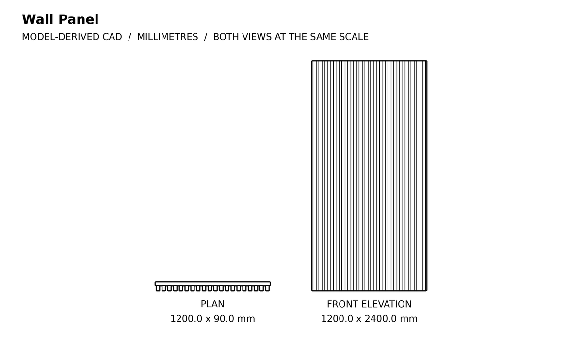
Download a free wall panel CAD block with a top plan and front elevation. Every drawing is a millimetre-scale DXF that opens in AutoCAD. Free commercial use, no signup.
Free DXF downloads
Quick answer: Wall Panel: one AutoCAD R2013 DXF containing named PLAN and ELEVATION blocks, inserted side by side at scale 1. Downloads contain DXF in a ZIP, not DWG. Extract the ZIP first. AutoCAD opens DXF directly; use Save As if you need a DWG copy.
Download Wall Panel DXF in a ZIP · 9.5 KB
Millimetres · $INSUNITS=4 · separate reusable plan and elevation blocks · no external textures or references. Captions sit outside the blocks.
Read the pack README and commercial-use license.
Layout and placement notes
Use the wall panel CAD block for architectural layout studies. Its top plan measures 1,200 mm (47.24 in) × 90 mm (3.54 in) and the front elevation measures 1,200 mm (47.24 in) × 2,400 mm (94.49 in). Both views are reusable named blocks in a millimetre-scale AutoCAD R2013 DXF, supplied in a ZIP. Check the drawing extents and any symbolic additions before placing it in a project.
The slat arrangement is illustrative, not a fixing or acoustic detail. Coordinate backing, joints, sockets and fire-performance requirements independently, and distinguish the finish depth from the wall structure behind it.
Dimensions and layers
| View / measurement | Millimetres and inches |
|---|---|
| PLAN drawing extents (width × depth) | 1,200 mm (47.24 in) × 90 mm (3.54 in) |
| ELEVATION drawing extents (width × height) | 1,200 mm (47.24 in) × 2,400 mm (94.49 in) |
| Physical source mesh width | 1,200 mm (47.24 in) |
| Physical source mesh depth | 90 mm (3.54 in) |
| Physical source mesh height | 2,400 mm (94.49 in) |
| DXF format / ZIP download size | AutoCAD R2013 in a ZIP / 9.5 KB |
Drawing extents include any swing or schematic symbols. Physical source bounds are listed separately; neither is a manufacturer's nominal or clear-opening dimension.
| Layer | Purpose |
|---|---|
| A-FURN-DETL | Visible interior features and component edges; 0.13 mm |
| A-FURN-OUTL | Closed silhouettes and openings; 0.25 mm lineweight |
| A-ANNO-TEXT | View captions outside the reusable blocks; 0.13 mm |
Most plans are true overhead projections, not floor-plan cuts: lintels and overhangs may hide lower details. Door operation symbols are deliberately schematic. Curves retain some source-model faceting; drawings are layout aids, not construction details.
How to insert the DXF
AutoCAD: open DXF or insert as a drawing block
Open the DXF directly and run UNITS: insertion units should be millimetres. In a millimetre project, insert at scale 1. Use INSERT for the whole drawing or copy the required PLAN/ELEVATION block. To merge several files, insert each whole file as its own named drawing block or rename the nested PLAN and ELEVATION definitions first to avoid block-name collisions. AutoCAD can save the drawing as DWG; this library supplies DXF only.
Revit: import 2D CAD at millimetre scale
In the intended plan or elevation view, choose Insert → Import CAD, select the DXF, set Import Units to millimetres and use Current view only when appropriate. The file contains both views side by side: prepare a view-specific copy or control visibility before placing it. It is 2D linework, not a parametric Revit family.
SketchUp: DXF import in a supported edition
Use a SketchUp edition that supports CAD import. Choose File → Import, select DXF, open Options and set the units to millimetres. Import into an empty model first, retain grouping, then move the required view into your project. These lines do not become a furnished 3D model; use the linked 3D asset for that.
ArchiCAD: open or merge with a DXF/DWG translator
Open or Merge the DXF and choose a translator with drawing units set to millimetres. Check the layer mapping and block handling in a scratch file, then use the required 2D view in the project. Confirm a known width using the dimension table before duplicating the symbol.
Working in inches: 1 inch is exactly 25.4 mm. Convert once on import, or scale millimetre coordinates by 1/25.4 in an inch-based drawing. Do not both auto-convert units and manually scale again.
Render your design
After arranging the blocks, export a clean plan or compose a scene with the matching 3D models. Upload a supported image or SketchUp view to Render a House to explore a rendered design. Do not upload a DXF expecting it to become an editable BIM model; keep the original CAD drawing as the dimensional reference.
License
Free for personal and commercial projects. No signup or attribution required. Do not resell or redistribute the files as a standalone pack or another asset library. Provided as-is without warranty: not manufacturer-certified products, engineering assemblies or construction documentation.
Frequently asked questions
How should I place the wall panel CAD block?
- The slat arrangement is illustrative, not a fixing or acoustic detail. Coordinate backing, joints, sockets and fire-performance requirements independently, and distinguish the finish depth from the wall structure behind it.
What are the plan and elevation dimensions of this wall panel?
- The plan is 1,200 mm (47.24 in) × 90 mm (3.54 in) (width × depth). The front elevation is 1,200 mm (47.24 in) × 2,400 mm (94.49 in) (width × height). These are drawing extents, including any symbolic additions; they are not a manufacturer's nominal size.
Is this a DWG download or a DXF file?
- Each download contains AutoCAD R2013 DXF in a ZIP, not DWG. Extract the ZIP, then open DXF in AutoCAD; use Save As and choose DWG if needed. No native DWG files or DWG converter are included.
What units and insertion scale should I use?
- The drawings use millimetres with $INSUNITS=4. Set the destination drawing to millimetres and insert at scale 1. If the destination uses inches, convert once using 1 inch = 25.4 mm; do not relabel the units without scaling geometry. PLAN and ELEVATION are separate named blocks in each drawing.
Can I use the CAD blocks in commercial projects?
- Yes. Personal and commercial projects are free, without signup or attribution. Do not resell or redistribute the drawings as a standalone pack or another asset library. They are provided as-is, not as manufacturer, engineering or construction documentation.
Related CAD blocks and 3D model
Need the object in three dimensions? Download the matching Wall Panel 3D model in GLB, FBX and OBJ.
Other blocks in the same category:
Jali CAD block
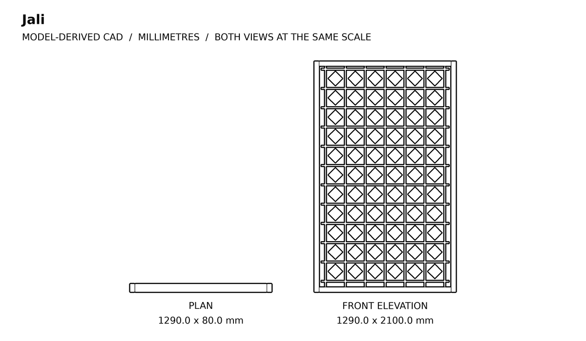
Plan 1290 × 80 mm · front elevation included
Download DXF in a ZIP · 10.9 KB